PANEL POSITIONING
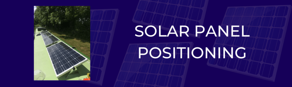
In an ideal world we strive to get the panels in a row on the centre line as you can see in photo 1 above and start as close to the aft end of the boat as possible, this reduces ugly cabling and is a safer place for panels as more control can be had over what the back of the boat does, as opposed to the front. Our tilting brackets allow the panels to ride over the roof vents.
This has the advantage that they are easy to walk by and importantly do not shade each other when tilted. On wide beam boats, with more roof space and typically bigger systems as wide beams tend to be more power hungry, we tend to locate the panels in two rows side by side, again taking care to make sure the gap is wide enough so when tilted they do not shade each other. You can see this in photo 2 of a 6 panel system on a wide beam. Sometimes we can get say two panels aft of the centre line, then a gap for the centre line and then one or two in front of the centre line (depending on system size of course) In our front page you will see variations on this due to compromising situations, lack of roof space, opening hatches, etc.. However we always strive to ensure panels are not in a place where they are in the way, or able to shade each other.
The table below summarises the systems available. Keep in mind all the systems are basically the same but made up of either two, three or four panels (430W, 645W, 860W). All are made up of multiple 215 Watt latest generation Victron Blue Solar low voltage panels of grade A mono crystalline design. Dimensions are 1590mm x 800mm but remember our tilting bracket system (see tab) allows them to ride over any roof vents and installed on the centre line leaves room to get past them if working off the roof. Note the Max amps is what can be achieved on a perfect day with direct sunlight, and is dependant on the batteries demanding a high charge.
SAFETY AND MASTER SWITCH SYSTEMS INCLUDED
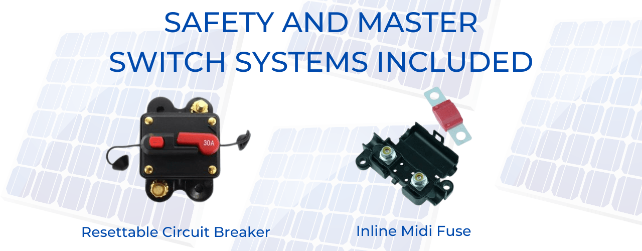
All our systems are installed with safety and convenience in mind and are fully compliant with BSS. We use an inline midi fuse on the battery connection (picture 2), located as required close to the batteries, we use a resettable circuit breaker (picture 1) on the solar line close to the controller, this protects against panel or panel cable faults plus this circuit breaker conveniently allows the solar charge to be switched off if required such as when changing batteries and thus acts as the solar master switch. The replaceable fuse on the battery line complies with BSS. A fault on the battery line though rare is a potential higher risk event hence a fuse is used not a circuit breaker as it has to be replaced. In reality these safety systems should never be needed. Note that the higher voltage of 37.5v coming from the panels comes in at lower amps than the amps going from controller to batteries at lower voltage (up to 14.4 max).
PARALLEL SOLAR PANEL CONNECTION
All our panels now run at 37.5 volts which means they are connected in parallel. This means any one panel can be shaded and the rest of the array can run at full power output.